Continuous operation
Adsorption, desorption and cooling zones rotate continuously for stable production-line service.

Continuous VOC concentration paired with lower-temperature catalytic oxidation.
Pre-treated exhaust passes through the adsorption zone of a hydrophobic zeolite rotor. Most of the cleaned air is discharged, while a smaller heated stream releases the adsorbed VOCs into a concentrated flow.
The concentrated stream is preheated and oxidised in the catalytic chamber. This combination is designed for large air volumes with low VOC concentration where treating the full airflow thermally would be inefficient.
Adsorption, desorption and cooling zones rotate continuously for stable production-line service.
Only the concentrated desorption stream enters the catalytic unit.
Molecular-sieve adsorption supports reliable capture across suitable mixed-VOC duties.
Recovered oxidation heat can support rotor desorption and incoming-gas preheating.
Remove dust, aerosols and other contaminants before the rotor.
Capture VOC molecules in the zeolite adsorption zone.
Return approximately 85–95% of the treated airflow to the stack.
Release captured VOCs into a smaller concentrated stream.
Convert the concentrated VOCs to CO₂ and H₂O before final discharge.
Final sizing, materials, controls and safety provisions are selected from the exhaust or process data supplied for the project.
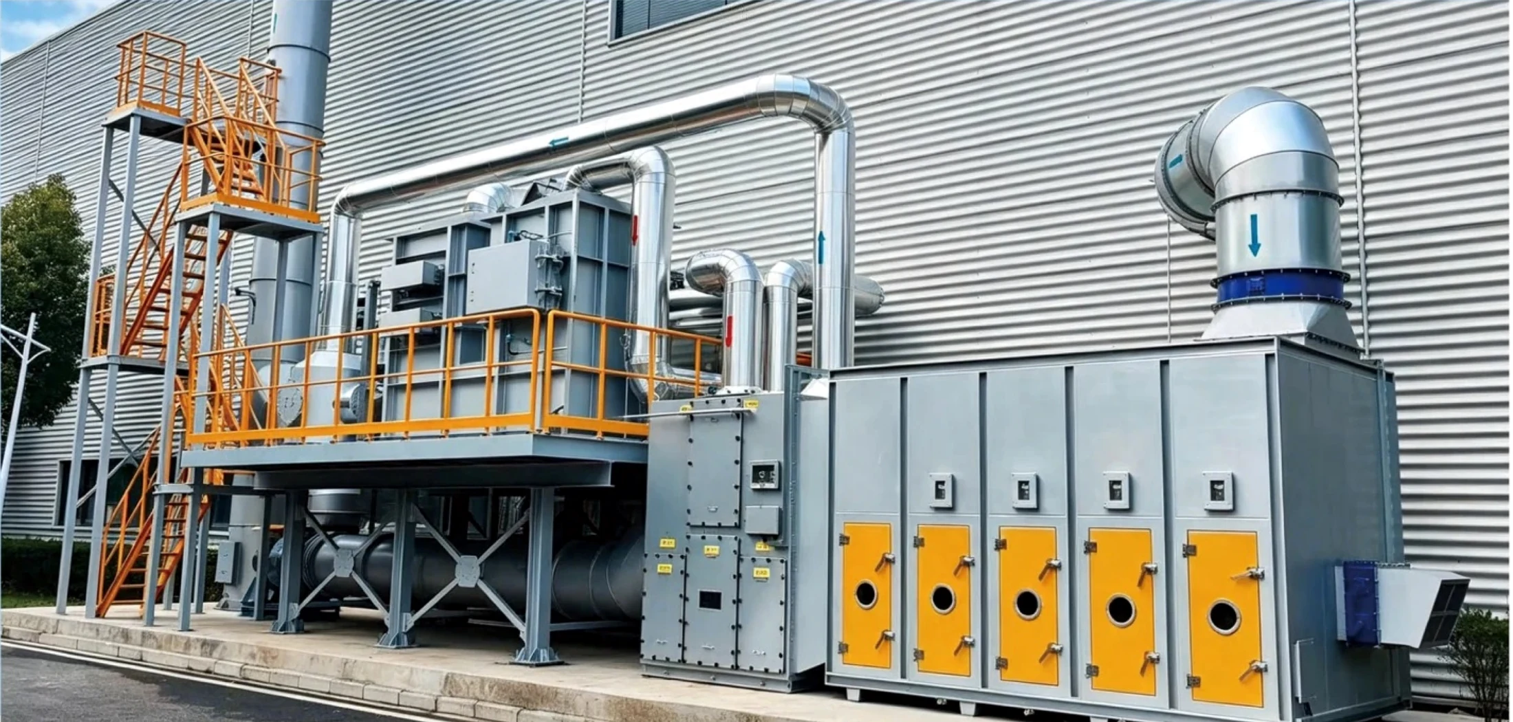
Final performance depends on verified process conditions. A technical proposal should not be based on equipment name or nominal airflow alone.
Provide the production process, pollutant composition, normal and peak concentration, temperature, humidity and any dust, mist or corrosive components.
State normal, minimum and peak airflow or treatment capacity, daily operating hours, batch cycles and expected future expansion.
Include available installation space, indoor or outdoor location, electrical standard, fuel or water availability, access constraints and project location.
Clarify whether the inquiry covers equipment supply, OEM manufacture, ductwork, controls, installation guidance, commissioning, training or spare parts.
Clean product assets extracted from the supplied source material. No translated brochure pages are embedded.
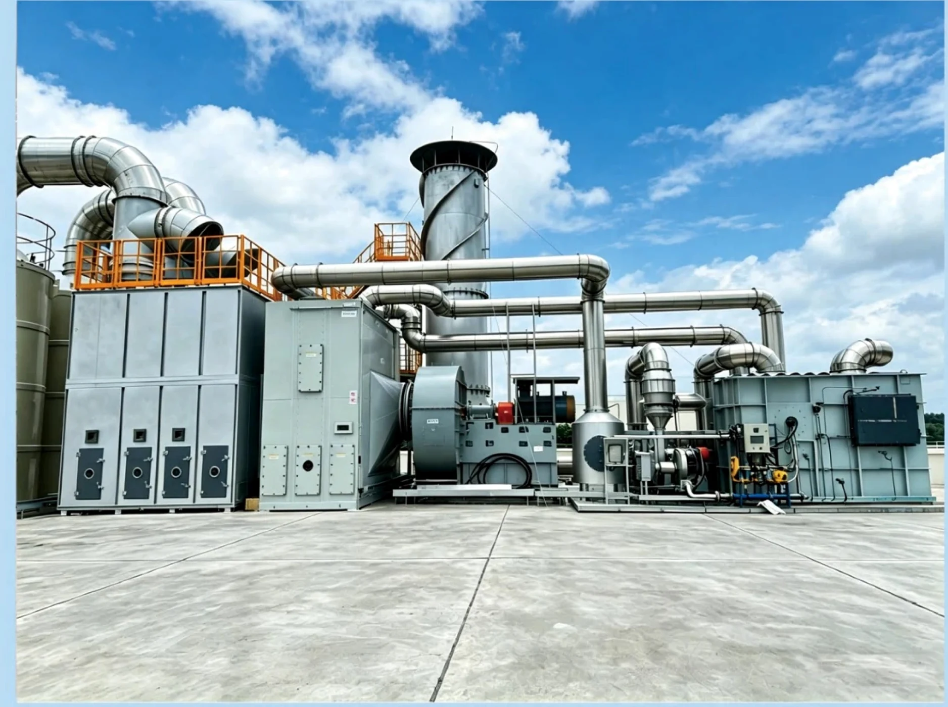
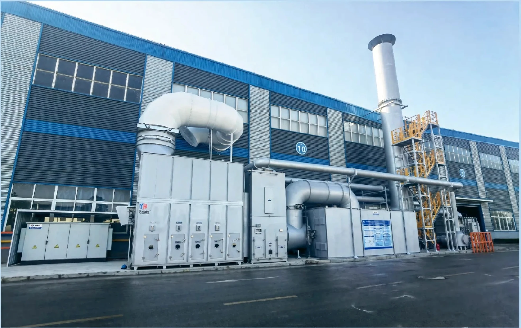
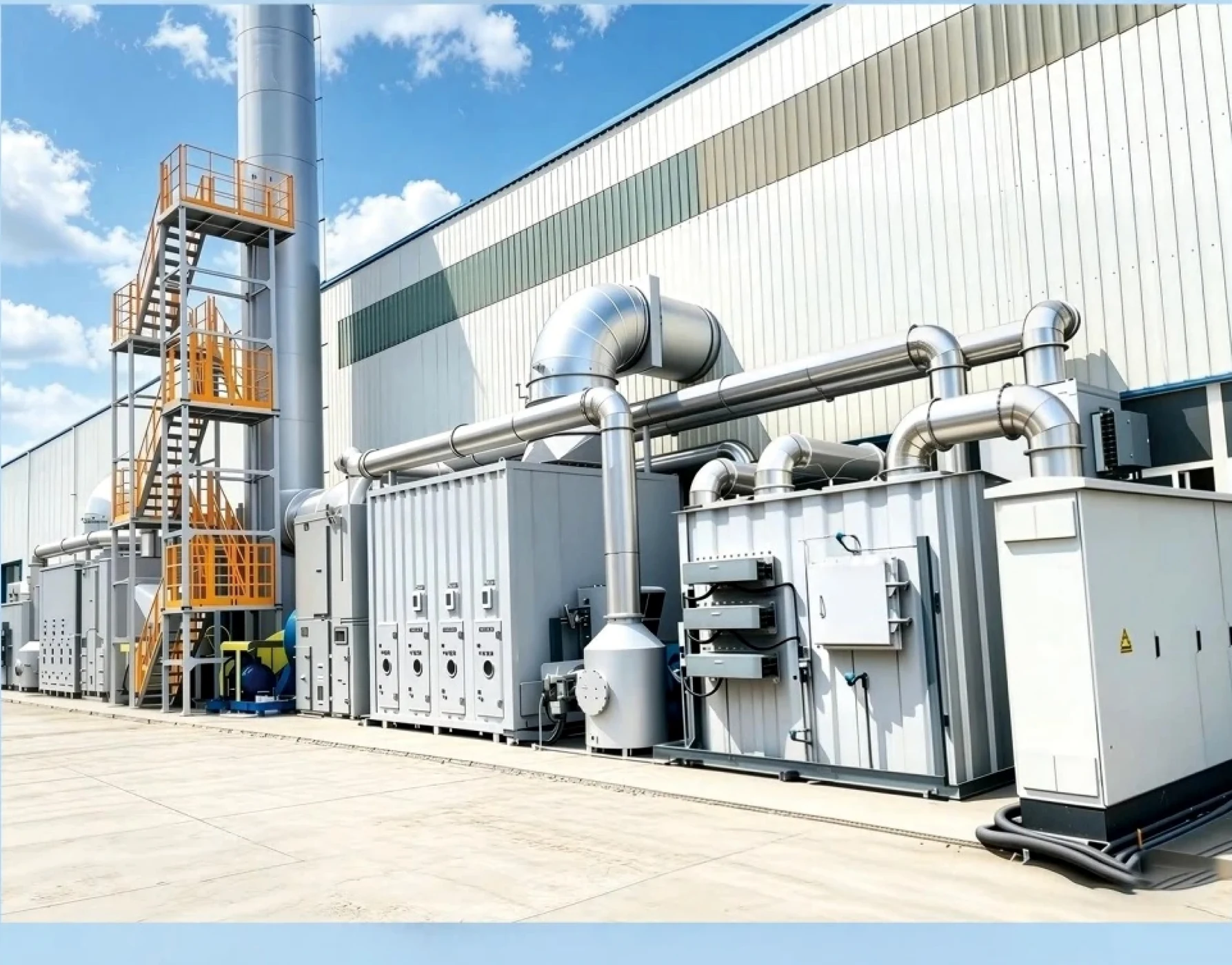
Share the airflow or capacity, pollutant composition, concentration, temperature, operating hours and site constraints. We will recommend the appropriate configuration.
Discuss your project →